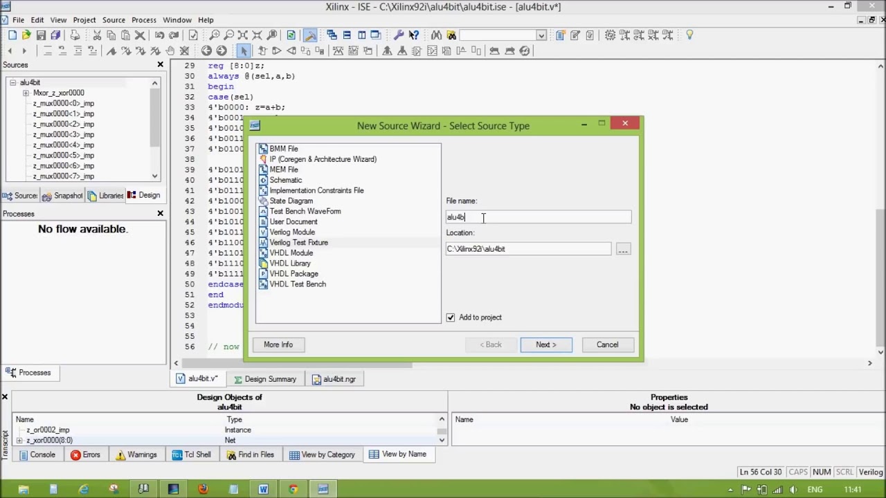
You can verify the working. Click OK to close the Tip of the Day window that pops up.

Verilog Code For Arithmetic Logic Unit Alu Fpga4student Com
To review open the file in an editor that reveals hidden Unicode characters.

. The gate voltage modifies the channel widt. 131230 07012013 Design Name. Full VHDL code for the ALU was presented.
0 out of 5 stars Digital Computer Arithmetic Datapath Design Using Verilog HDL. I am supposed to create 4 bit full adder verilog code in vivadoBut when I try to test in the simulationIt give me z and x outputWhich part of code I have to change to get an output in simulation. This is the simulation window.
The block diagram of the ALU is given below. CD-ROM included Reviewed in the United States on March 11 2008 I would have liked to review this book but unfortunately Amazon twice sent me a defect book that did not have the CD v The divider module divides one number by another Switch or case. We have also proposed several algorithms using different design levels.
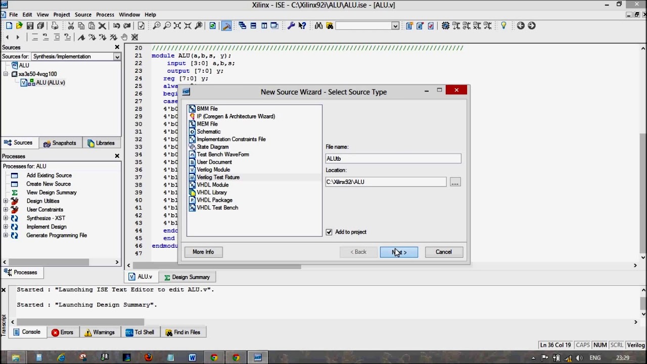
Include addition subtraction and shifting We proposed arithmetic and logic unit using VHDL structural and dataflow level design. Make sure you have installed Xilinx ISE 144 or later. Double-click on ALU to load the file.
Click to share on Twitter Opens in new window. Unfortunately for the 4-bit ALU it would be impractical to use discrete chips to create a 4-bit adder. Simulating the ALU design.
Verilog code Using Xilinx Software Neeraj Kulkarni neerajkiitkacin. N-bit Adder Design in Verilog. Module demux_2x1 input 310 a input s output 310 y0y1.
This should open a third tab sim in the main window. This research paper is based on the simulation of 16 bit ALU using VHDL. Preferable install it in Windows 7 environment.
It has 5-bit input consisting of four 2-bit AND gates inside. Mohd Kashif Create Date. An Arithmetic and Logic Uni t is a digital circuit which performs arithmetic logical and shift operations.
Click on Library menu from the main window and then click on the plus sign next to the work library. LIST OF FIGURES 11 TYPICAL DESIGN FLOW 3 22 Xilinx ISE Interface 9 31 32-bit Arithmetic unit 13 32 32-bit Logic unit 14 331 a 32-bit before Left Shift 15 b 32-bit after Left Shift 16 332 a 32-bit before Right Shift 16 b 32-bit after Right 16 333 32-bit Shift unit 17 34 Arithmetic Logic Unit 19 41 RTL of 32-bit ALU 44 42 4. This video describes the complete simulation flow step by step for VHDL Code using Xilinx ISE Design Suite 147 It helps beginners to understand the working.
Follow the below-mentioned procedure to simulate your first Verilog program. Arithmetic Logic Unit ALU is one of the most important digital logic components in CPUs. ALU Behavioral Project Name.
The result is denoted by R which is also 8 bit long. A full adder made by using two half adders and an OR gate. It is the fundamental building block of central processing unit CPU.
Assign COUT A. It can be used in integer arithmetic computations and as Complex operation. Let us design a simple ALU using some arithmetic and logical operators.
Simulation Result for 4-bit ALU. Verilog code for multiple bit input demultiplexer. The 4 outputs of each unit are connected to 4 inputs of the 4 AND gates.
Each module of ALU is divided into smaller modules. In this Video you will learn how to design or implement the 4 bit ALU in verilog using Xilinx Simulator in very simple waySee Code here httpwww2dixco. Explain by Examples 32.
N-bit Adder Design in Verilog 31. Xilinx 144 has some annoying bugs when run with Windows 8. You can uncheck Show Tips at Startup if you do not want the.
The testbench Verilog code for the ALU is also provided for simulation. Ive created and tested the code for a 1-bit Half Adder a 1-bit Full Adder a 4-bit Ripple Adder and 2s complement coding. Controlled by the three function select inputs sel 2 to 0 ALU can perform all the 8 possible logic operations.
4-bit ALU Module Name. 4x2-bit AND AKA 5-bit AND in our project files. 4 bit ALU Design in verilog using Xilinx.
The body terminal is there whether we like it or not because of the construction of a MOSFET. Design methodology has been changing from schematic design to HDL based design. Assign S ABCIN.
An ALU performs following operations Addition subtraction multiplication Not logical shift. This file contains bidirectional Unicode text that may be interpreted or compiled differently than what appears below. Adapted from this image.
The behavioural modeling in VHDL is same as VERILOG except the keyword always is. Use of BODY terminal in MOSFET. Jan 20 2018 - Verilog code for Multiplexers.
You can pick these up for a few dollars on eBay. I think they still do not support windows 8. How to generate a clock enable signal in Verilog 34.
The project is a 4-bit ALU in VHDL with a total of 16 operations which includes various arithmetic logical and data calculations performed by coding the ALU in VHDL code. There are six 4x2-bit AND blocks one for each main function. Verilog code for Clock divider on FPGA 33.
Digital Clock manager DCM in Xilinx FPGA. The design was implemented using VHDL Xilinx Synthesis tool ISE and targeted for Spartan device. Fig 2RTL view of 4 bit ALU.
This paper presents design concept of 4-bit arithmetic and logic unit ALU. You should see the name Top_ALU code that we have just compiled Fig. The approach used here is to split the ALU into three modules one Arithmetic one Logic and one Shift module.
Module my_full_adder input A input B input CIN output S output COUT. The input signal Op is a 3 bit value which tells the ALU what. In this Video you will learn how to design or implement the 4 bit ALU in verilog using Xilinx Simulator in very simple waySee Code here httpwww2dixco.
Xilinx ISE 146. Functional Description of 4-bit Arithmetic Logic Unit. So we will cheat and use a 4008 4-bit adder IC.
4008 4-bit full adder pinout. In this paper we have proposed efficient VHDL behavioural coding verification method. For this tutorial we have Xilinx ISE 144.
As you can see it receives two input operands A and B which are 8 bits long. Open 3264-bit Project Navigator. Our proposals have been implemented in Verilog and verified using Xilinx ISE 101 analyzer.
Up to 24 cash back Im struggling with the code to make a 4-bit ALU in Verilog.

Exp 4 4 Bit Alu Implementation Using Xilinx Fpga Youtube

Xilinx Ise Full Adder 4 Bit Verilog Youtube

Alu Design In Verilog With Testbench Simulation In Modelsim Arithmetic Logic Unit Youtube
4 Bit Alu Design In Verilog Using Xilinx Simulator Youtube
Xilinx Ise 4 Bit Alu Add Subtract Verilog Youtube

Design And Analysis Of Fpga Based 32 Bit Alu Using Reversible Gates Semantic Scholar

Vhdl Code For Counters With Testbench Vhdl Code For Up Counter Vhdl Code For Down Counter Vhdl Code For Up Down Counter Coding Counter Counter Counter
Alu Design In Verilog With Text Bench Youtube
0 comments
Post a Comment